
Search LEMIX Products
Explains best practices for producing highly filled compounds through optimized feeding, venting, screw configuration, and filler incorporation.
Category:Materials & Applications
Author:LEMIX Admin
Date:2026-06-29
Overview
Follow these best practices for compounding highly filled polyolefin compounds in twin-screw extruders, taking into account air entrainment, venting challenges and optimal filler incorporation.
Highly filled compounds such as polyolefins filled with calcium carbonate or talc can have mineral filler contents of 70-80% by weight and even higher, especially for calcium carbonate compounds. These compounds are often used as masterbatches for other processes. Because these mineral fillers are usually fed via two to three side feeders, a considerable amount of air is introduced into the twin-screw extruder. This becomes increasingly challenging, especially for mineral fillers with low bulk densities. Since the polyolefin content of such compounds is less than 30%, the torque requirements of the twin-screw extruder are not very high, as less than 30% of the mixture is polymer pellets that need to be melted.
Extruders with high free volume are best suited for compounding these high mineral content materials. High free volume is the open volume between the screws and the barrel. Free volume is controlled by the ratio of the outer screw diameter (Do) to the inner screw diameter (Di), as shown by Figure 1. A higher ratio creates deeper channels and higher free volumes. A higher Do/Di ratio allows the rate of the extruder to be increased.
Figure 1: Schematic of a conveying screw segment showing the outside diameter (Do), the inside diameter (Di), and the free volume of screw elements. Source: KraussMaffei Extrusion
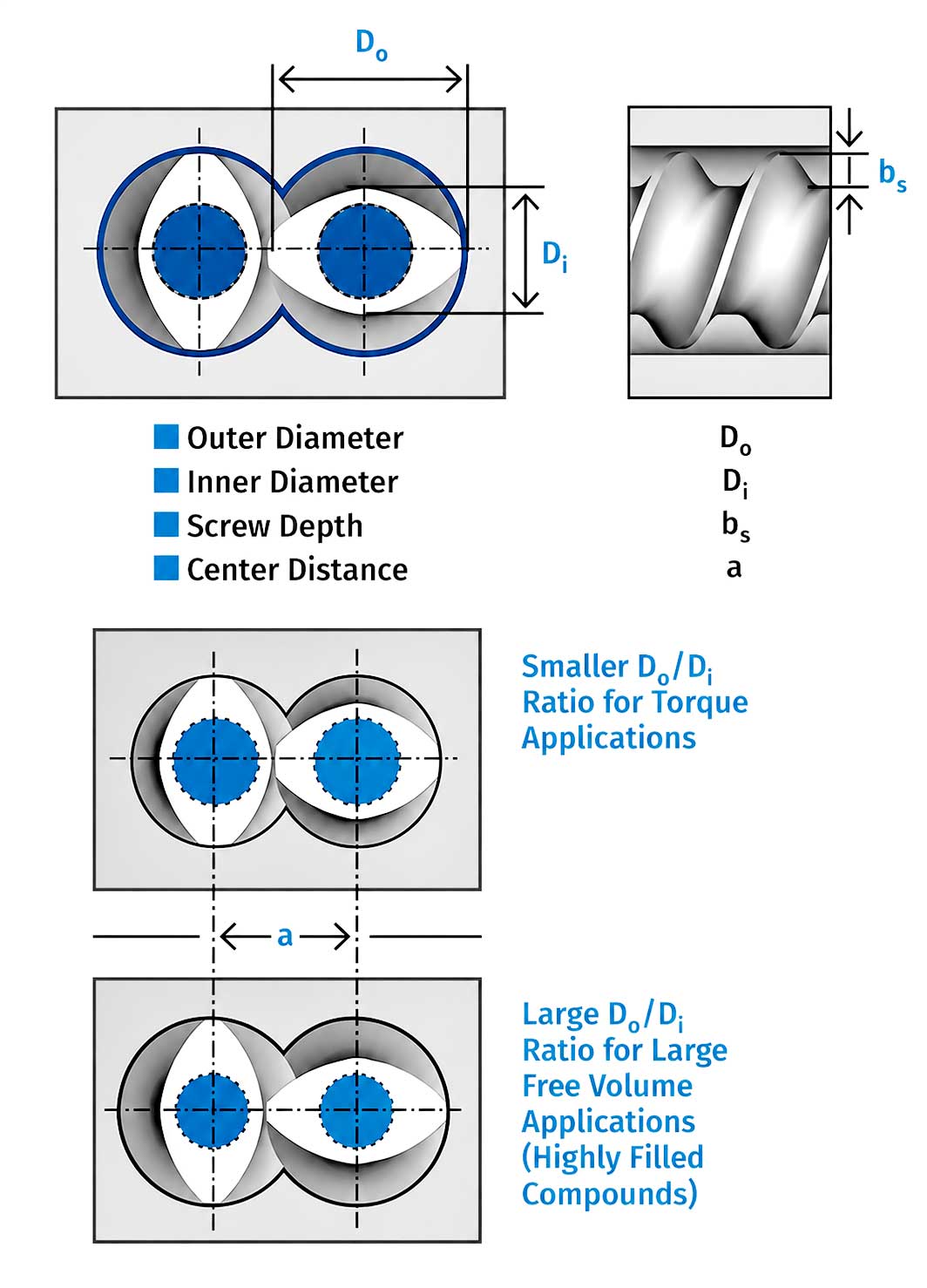
Typically, the ratio should be 1.65 or higher. There are large free-volume extruders available with a Do/Di ratio up to 1.80. The two main challenges of highly filled compounds are feeding the mineral filler from the side feeders into the twin-screw extruder without causing vent flooding and incorporating the high filler content homogeneously into the polyolefin matrix without forming filler agglomerates in the final compound.
Air is entrained with low bulk density fillers. The key is to introduce as little air as possible into the extruder during filler feeding and to vent the air out of the extruder without expelling filler particles through the vents. For example, a low bulk density mineral filler was being compounded into a PE resin. The air entrainment was very high, and the process conditions were not optimal, causing some filler to be expelled out through the vent opening, as shown by Figure 2. The unincorporated filler created health hazards, housekeeping issues and difficulties in maintaining the filler level in the product.
Figure 2: Photograph of mineral filler exiting a downstream vent opening. The trunk over the top of the vent was positioned to exhaust air and vapor. Here it is also exhausting unincorporated filler. Source: R. Segiet
Where To Place Feeder
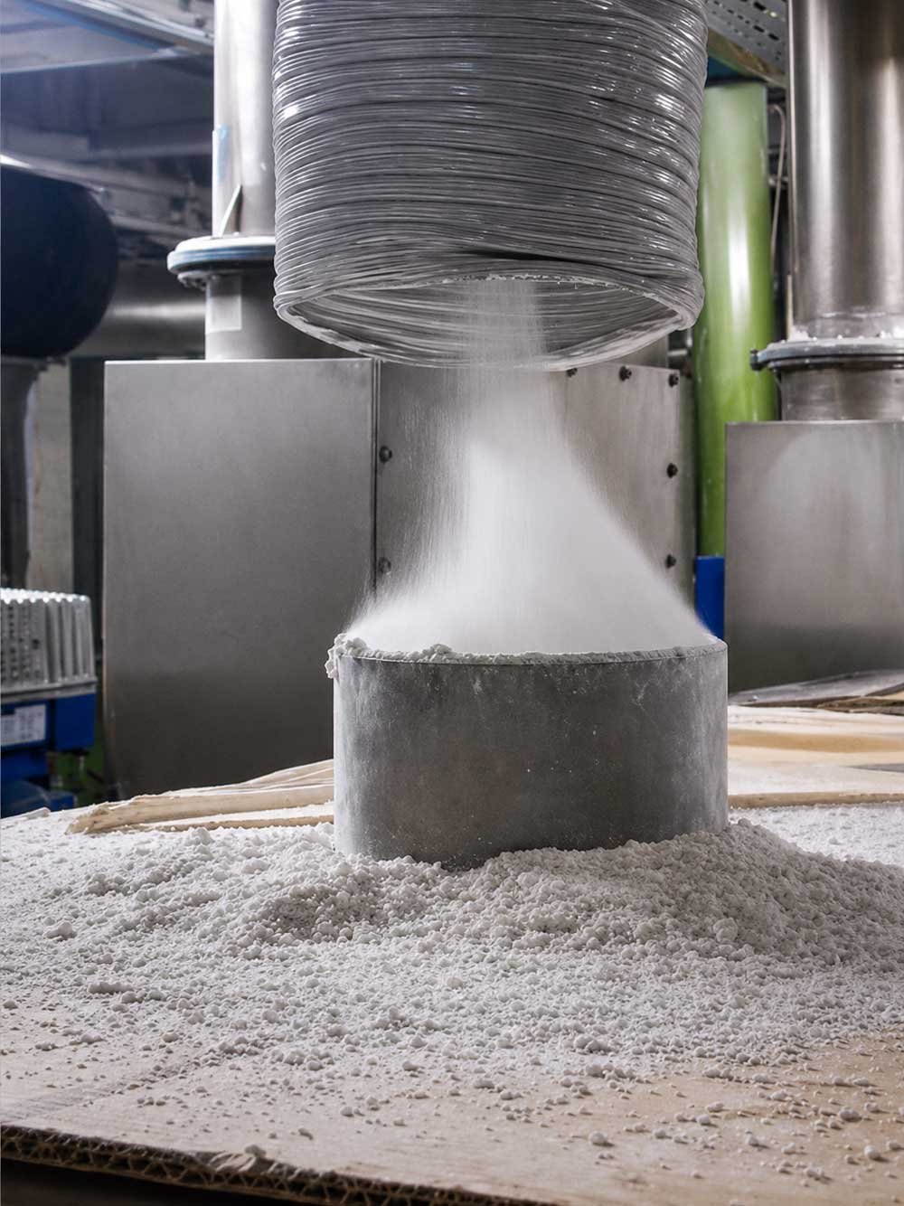
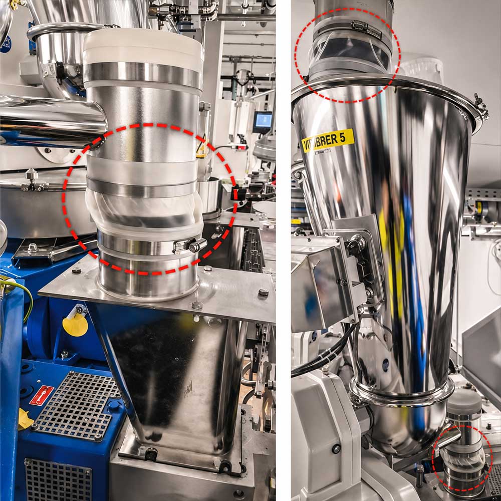
The lower the bulk density of the mineral filler, the more air is introduced into the extruder when feeding via a side feeder. To minimize this air intake, the loss‑in‑weight feeder should be placed as close as possible above the side‑feeder hopper so that the filler powder does not become aerated during its free-fall transport through the feed pipe, decreasing the bulk density. Ideally, the powder loss‑in‑weight feeder should be directly connected to the side‑feeder hopper using a flexible sleeve (bellow).
It is crucial that these sleeves are not installed under tension, as this would drastically impair the accuracy of the gravimetric loss‑in‑weight feeder. The same applies to the sleeve at the inlet hopper of the loss‑in‑weight feeder. Photographs of flexible sleeve connectors are shown in Figure 3.
Photographs of flexible sleeve connectors at the top of the feed hopper (right) and at the feed pipe to the side feeder (left). Source: R. Segiet
Moreover, the conveying screws (twin-screws) of the side feeder should run as slowly as possible and only slightly faster than the minimum required to ensure that mineral filler does not back up in the side‑feeder hopper. Running them slowly helps keep the screw channels of the side‑feeder fully filled, which reduces air intake into the extruder. However, even with the gentlest possible powder handling into the twin‑screw extruder, air will always be introduced due to the low bulk density of the mineral filler. This is unavoidable.
As shown by Figure 2, the entrained air entering the twin‑screw extruder must be vented without expelling mineral filler powder out through the vents. To achieve this, a back vent port is located upstream of the side‑feeder barrel section, and a front vent is placed further downstream, after the mineral‑filler incorporation section. A schematic of this configuration is provided in Figure 4. For the air to be vented effectively through both the back and front vents, the screws of the twin‑screw extruder must be axially open in this region. This means the extruder must be partially filled (starved) in this section.
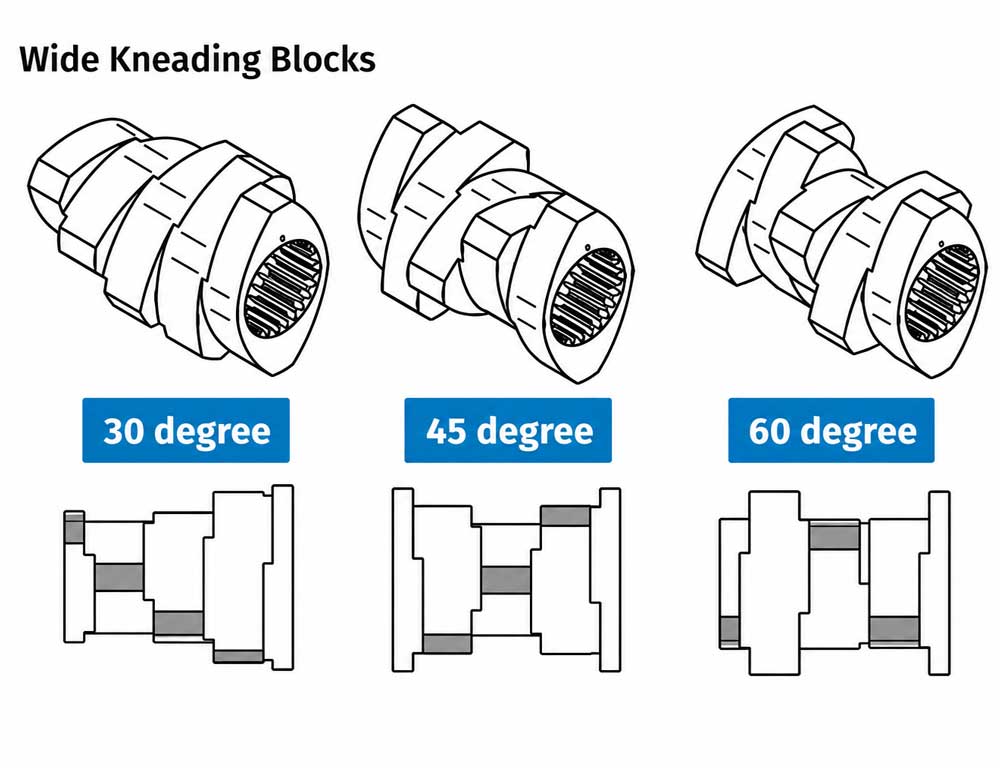
If the mineral filler is not conveyed downstream quickly enough, it may not be incorporated into the polymer melt matrix fast enough. This can also lead to blocking of the back vent. If this is the case, it may help to use a wide kneading block with a conveying 30-degree staggering disc angle instead of the commonly used 45-degree for the first kneading block after the side feeder. The 30-degree staggering angle conveys the mineral filler slightly faster downstream than the 45-degree, which can eliminate back‑vent flooding in borderline processing conditions. Schematics for wide kneading blocks are shown in Figure 5.
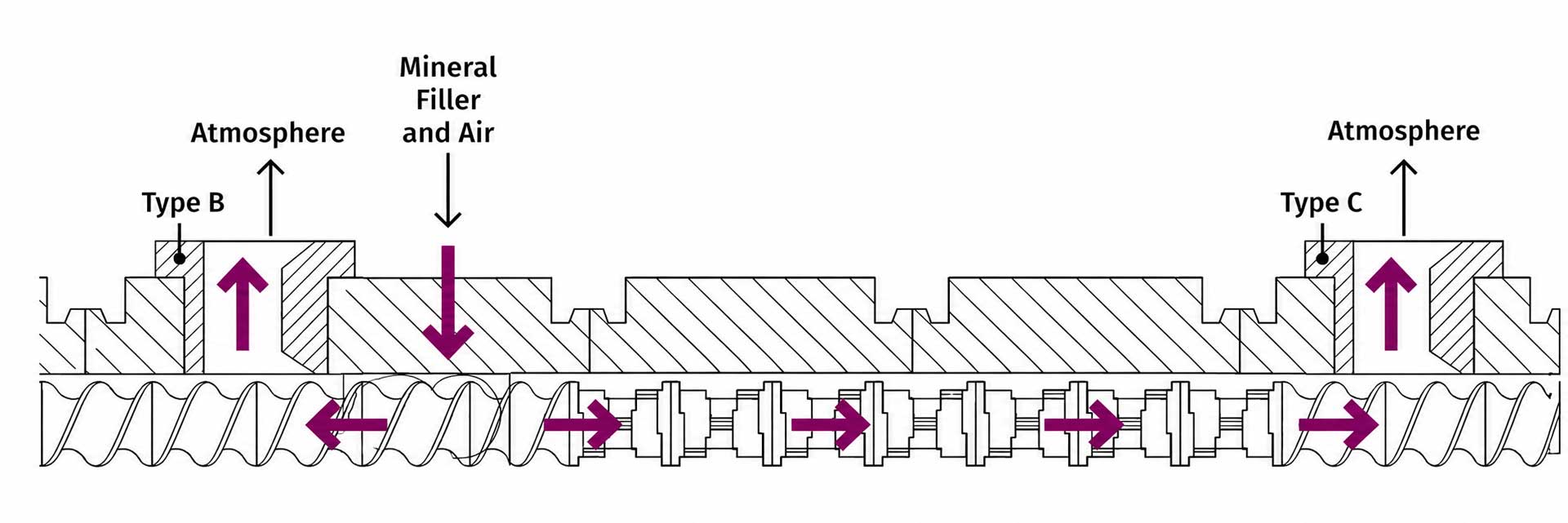
Schematic for the screw design, vent positions, and side feeder location for optimal venting of entrained air. The colored arrows show the flow paths of the entrained air. Source: R. Segiet
The front vent can also be flooded by mineral filler. This typically happens when the filler is not fully incorporated into the polymer matrix in the incorporation section. The underlying reason is either that the incorporation section is too short for the amount of mineral filler fed through the side feeder or that the total rate is too high for the extruder size.
Try Wide Kneading Blocks
If the process is only borderline, meaning only a small improvement is needed to achieve proper incorporation of the mineral filler into the polymer matrix, a wide kneading block with a 60-degree staggering disc angle could resolve the issue. The wide kneading block would be the first kneading block after the side feeder. The 60-degree staggering angle slightly reduces the conveying capacity, which in turn increases the residence time and the degree of fill in the block.
If the level of the mineral filler is too high for a given section, then the distribution ratio of the mineral filler across the two to three side feeders must be adjusted. This adjustment also applies when flooding of the back vent cannot be resolved using the optimization measures described earlier.
Schematic of 30-, 45-, and 60-degree wide kneading blocks. Source: R. Segiet
Sometimes a portion of the mineral filler can be added through the main feed barrel together with the polymer and additives into the twin‑screw extruder. Alternatively, a portion of the filler could be added via a side feeder positioned immediately after the main feed hopper. These configurations are shown in Figure 6.
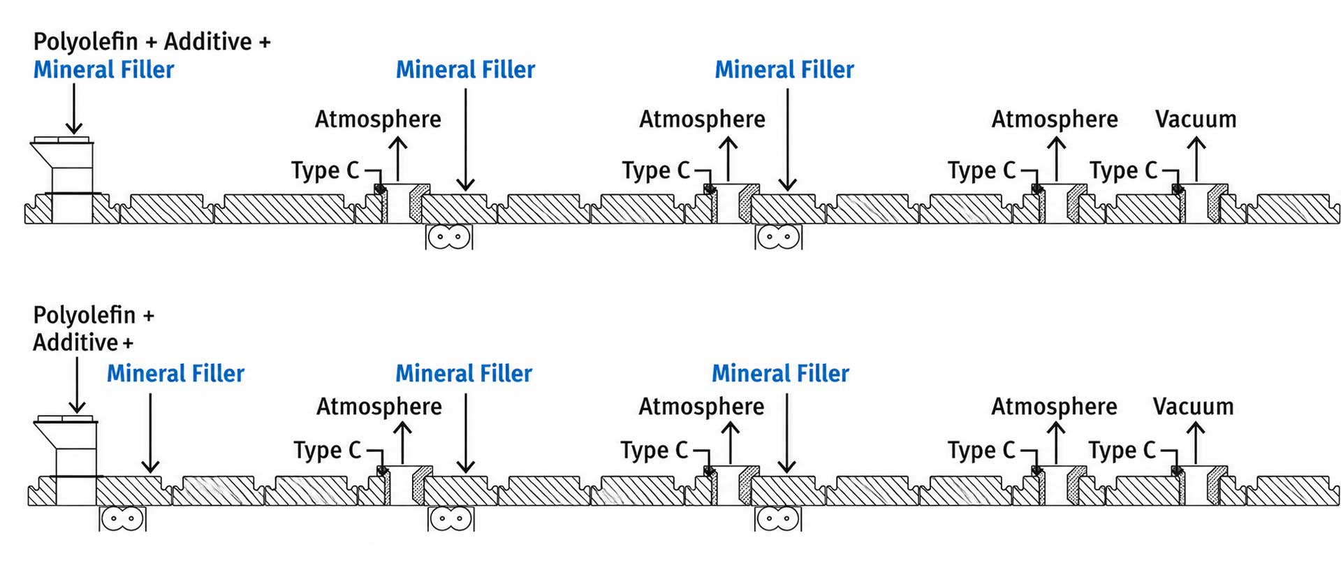
Figure 6: Schematics for adding a portion of the filler to the main feed hopper (top) and adding just downstream of the hopper using a side feeder (bottom). Source: R. Segiet
Depending on factors such as the polymer viscosity, the particle size of the mineral filler, filler bulk density, the moisture level of the filler and other material-specific properties, the distribution of mineral filler between the side feeders and the main feed section must be adapted. As the mineral filler content increases, determining the optimal distribution becomes increasingly challenging. The moisture level of the filler should be kept as low as possible, otherwise, in addition to the air already introduced, water vapor will form inside the extruder and increase the likelihood of vent flow and blocking.
The level of mineral filler that can be added through the main feed section is limited for two primary reasons, including restricted venting capacity and the risk of filler agglomeration. In this section, there is no axially open screw zone through which the introduced air can be released via a front vent. This is because the downstream melting section is fully filled, and any air introduced with the mineral filler must travel backward and escape through the main feed hopper where the venting capacity is limited.
A higher level of mineral filler level in the feed zone has a greater risk of agglomerating the filler, especially when the polymer level becomes low. As the mineral filler powder enters the melting section together with the solid polymer pellets, it becomes compacted and compressed. Some of these compacted filler agglomerates become so dense that they cannot be fully broken down again and remain as defects in the final compound. (For more on filler agglomeration, see the November 2025 issue.)
Adding a certain amount of mineral filler through the main feed, however, can sometimes improve the downstream incorporation. A small filler level in the polymer matrix can make the melt structure more receptive to additional mineral filler added later. That is, the first side feeder after the melting section can incorporate a higher level than would be possible if no filler had been pre-added through the main feed.
Adjust Screw Configuration as Needed
It is important to note that the required setup depends heavily on the specific polymer and mineral filler being processed. Adjustments to the twin-screw extruder configuration and to the composition and distribution of the mineral filler must be made on a case by case basis. Even if the overall mineral filler content of two formulations is identical, differences in polymer type or filler type may require different process conditions to achieve a high-quality compound.
Finally, an additional performance improvement can be achieved by installing a kneading block at the end of the pressure-build-up section before a melt pump. In this fully filled region, the kneading block introduces extra dispersive mixing (with a slight increase in melt temperature), which can help if the compound is nearly but not fully homogeneous.
For highly filled compounds, the use of a melt pump is strongly recommended, if not mandatory, especially as the mineral filler content increases. At very high filler levels, the compound becomes extremely viscous and “stiff,” which generates significant discharge pressure at the end of the twin‑screw extruder before the material is pushed through the die plate. This elevated pressure can cause a vacuum‑vent block if the melt pressure in front of the die increases enough to propagate upstream to the vacuum port. In addition, the melt temperature would increase drastically due to the high pressure at the end of the extruder. The mechanical wear on the barrel liner and screw elements in the pressure‑build‑up section also increases significantly with higher pressures.
A melt pump decouples the end of the twin‑screw extruder (the pressure‑build‑up section) from the die plate. This prevents melt backup from causing vacuum‑vent blockage and reduces the discharge temperature substantially. Typically, the inlet pressure of the melt pump is set to around 150-300 psi (10-20 bar).
Compounds with high mineral filler contents can be less effective at lubricating the bearings on melt pumps. Adequate lubrication is essential for the pump’s long‑term reliability. Therefore, not every melt pump is suitable for highly filled compounds. One must select a melt pump specifically designed and rated for use with high-filler formulations.
Source from: ptonline:《How To Produce Highly Filled Compounds on Co-Rotating Twin-Screw Extruders》by THE AUTHORS: Roman Segiet&Mark A. Spalding
Disclaimer: Some data, charts and other contents in this article are sourced from the Internet and other publicly published materials, which are only for readers' reference, communication and study, and not for any commercial activities or purposes. All copyrights belong to the original authors and original sources. If any copyright holder believes that this article involves infringement or other issues, please contact us for timely handling.