
Search LEMIX Products
Learn how screw configuration affects mixing, shear, and residence time in twin screw extrusion, including conveying elements, kneading blocks, venting, fill level, HME, scale-up, and LEMIX support.
Category:Extruder Technology & Selection
Author:LEMIX Admin
Date:2026-08-12
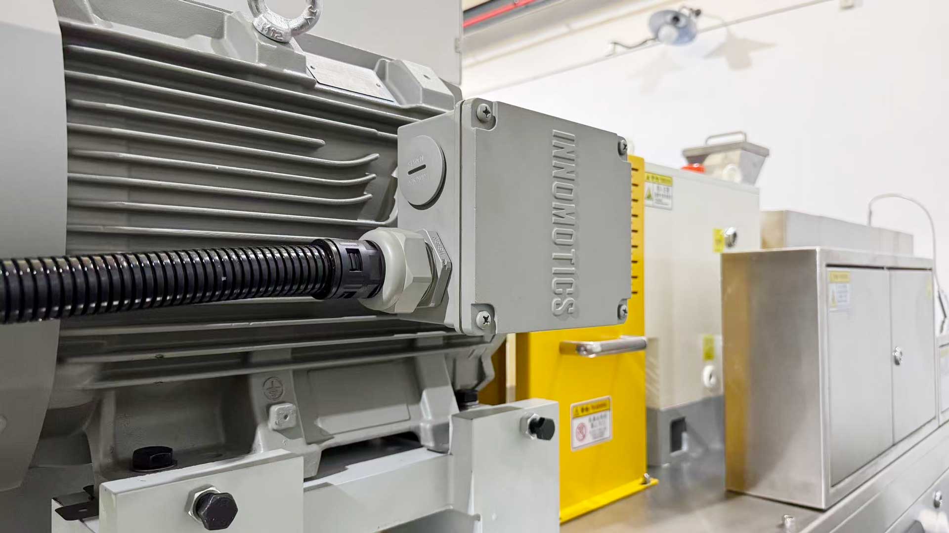
Screw configuration affects mixing, shear, and residence time by changing how material is conveyed, compressed, kneaded, vented, and discharged inside the barrel. Conveying elements move material forward, kneading elements increase mixing and shear, and restriction or venting sections change fill level and residence time.
Screw configuration is the arrangement of screw elements on the twin screw shafts. It defines how material moves through the extruder from feeding to discharge.
A twin screw extruder does not use one fixed screw shape for every material. It uses modular screw elements that can be combined for conveying, melting, kneading, distributive mixing, dispersive mixing, venting, pressure building, and discharge.
In practical production, screw configuration is one of the most important process design tools. It decides whether a material is gently transported, strongly mixed, deeply dispersed, quickly discharged, or held longer inside the barrel.
LEMIX twin screw extruders use a modular screw system. Screw material and screw combination can be customized according to materials and formulas.
Internal link: Twin Screw Extruder
Screw configuration matters because the same machine can behave very differently with a different screw layout. The motor, barrel, feeder, and temperature settings may remain the same, but mixing quality, torque, shear heat, venting efficiency, melt pressure, and residence time can change significantly.
A useful production view is this: screw configuration should be read as a process timeline, not as a parts list.
Each screw section answers a process question:
Where should the material be conveyed?
Where should it begin to melt?
Where should additives be introduced?
Where should fillers or fibers be wetted?
Where should strong mixing happen?
Where should shear be limited?
Where should moisture or volatiles escape?
Where should pressure be built before the die?
Where should residence time be shortened or extended?
This is why copying another factory’s screw configuration is risky. A configuration that works for one resin, filler loading, API-polymer blend, or cable compound may not work for another formula.
Twin screw extrusion uses different screw elements for different process functions. LEMIX screw element options include conveying elements, kneading blocks, transition elements, special elements, barrels, die plates, breaker plates, degassing plugs, side-feeder plugs, adapters, shafts, and accessories.
| Screw or Process Element | Main Function | Typical Effect |
|---|---|---|
| Conveying element | Moves material forward | Lower shear, shorter residence time |
| Kneading block | Mixes, compresses, and disperses material | Higher shear, stronger mixing, higher torque |
| Transition element | Connects different screw sections | Smoother material transfer |
| Special element | Supports special mixing or process needs | Adjusts distribution, dispersion, or flow behavior |
| Side-feeder section | Adds fillers, fibers, or additives later | Reduces early overload and improves wetting |
| Degassing or venting section | Removes moisture, air, solvent, or volatiles | Improves pellet density and product stability |
| Discharge section | Builds pressure before die or pelletizing | Affects pressure stability and output |
Internal link: Screw Elements for TSE
Conveying elements mainly move material forward. They create lower shear than kneading blocks and are used in feeding, transport, melting transition, venting, and discharge sections.
Conveying elements affect mixing indirectly. They control how full the barrel is, how fast material moves, and how much time later mixing sections have to work.
If conveying is too strong, material may pass through the barrel too quickly. Residence time becomes shorter, and mixing may be weak. If conveying is too weak, material may accumulate, torque may rise, and the screw may become overfilled.
A good conveying section should:
Feed material smoothly
Avoid feed throat buildup
Support stable screw filling
Move material toward the melting zone
Prevent unnecessary shear heat
Keep enough residence time for later mixing
Maintain stable pressure before discharge
For heat-sensitive materials, conveying elements are useful because they can move material without adding excessive shear.
Kneading blocks increase mixing and shear. They are used when the material needs melting, filler wetting, pigment dispersion, API-polymer mixing, or additive distribution.
Kneading blocks can create two types of mixing:
Distributive mixing: Spreads materials evenly without necessarily breaking particles strongly.
Dispersive mixing: Breaks agglomerates, solid particles, or droplets into smaller structures.
Both types are useful, but they create different risks. Distributive mixing is usually better for heat-sensitive or shear-sensitive materials. Dispersive mixing is useful when pigments, fillers, APIs, or agglomerates must be broken down.
Too many kneading blocks can create excessive shear, high torque, frictional heat, material degradation, fiber breakage, vent flooding, and wider residence time distribution. Too few kneading blocks can cause poor dispersion, gels, unmelted particles, weak additive distribution, or unstable product quality.
The best kneading design is not the most aggressive design. It is the design that gives enough mixing without damaging the material.
Screw configuration controls shear by changing how much mechanical energy is applied to the material.
High-shear sections are created by tighter mixing zones, kneading blocks, reverse or restriction elements, and highly filled screw sections. Low-shear sections are created by open conveying elements, large-pitch transport sections, gentle distributive mixing elements, and lower filling zones.
Shear affects:
Melting speed
Filler wetting
Pigment dispersion
API-polymer distribution
Fiber breakage
Melt temperature
Torque
Residence time
Degradation risk
Final product performance
For engineering plastics and high-filler compounds, enough shear is needed to wet fillers and disperse additives. For TPE/TPU, pharmaceutical HME, thermoset premixing, PVC cable compounds, and heat-sensitive formulas, excessive shear can create defects.
A practical rule is to use shear only where it creates value. Strong shear should be placed where melting, wetting, or dispersion is needed. Gentle conveying should be used where the material only needs transport, venting, or discharge.
Residence time is the amount of time material stays inside the extruder. Screw configuration affects residence time by changing conveying speed, fill level, back pressure, mixing intensity, and dead-zone risk.
A configuration with many conveying elements usually creates shorter residence time. A configuration with more kneading, reverse, or restriction elements usually increases residence time because material is compressed, mixed, or partially held back.
Residence time is important because material quality depends on time under heat and shear.
Short residence time may cause:
Poor melting
Poor dispersion
Weak devolatilization
Unstable pressure
Incomplete API-polymer mixing
Filler agglomerates
Poor pellet quality
Long residence time may cause:
Thermal degradation
Yellowing
Black specks
API impurity formation
PVC decomposition
Premature curing in thermosets
Gel formation
Crosslinking risk in reactive systems
A stable process needs not only the right average residence time, but also a narrow residence time distribution. Material should not have dead zones where part of the formula stays much longer than the rest.
Fill level describes how much of the screw channel is occupied by material. It connects screw speed, feed rate, screw design, torque, shear, and residence time.
If fill level is too low, the screw may not mix efficiently. The material may move quickly, receive inconsistent shear, and create poor pressure stability. If fill level is too high, torque rises, vent sections may flood, pressure may become unstable, and shear heat may increase.
Screw configuration controls fill level by changing channel volume and flow resistance.
| Fill Level Condition | Typical Result |
|---|---|
| Underfilled screw | Weak mixing, low torque, shorter residence time |
| Properly filled screw | Stable mixing, controlled shear, repeatable output |
| Overfilled screw | High torque, pressure rise, vent flooding, longer residence time |
| Local overfilling | Hot spots, degradation, poor devolatilization |
| Local underfilling | Poor wetting, weak dispersion, unstable pressure |
A good screw configuration creates the right fill level in each process zone, not the same fill level everywhere.
Side feeding allows fillers, fibers, additives, or sensitive materials to enter after the base polymer has started to melt. This changes the screw design because the extruder must create a receiving zone for side-fed materials.
If fillers or fibers enter too early, they may increase friction, torque, screw wear, and feeding instability. If they enter too late, there may not be enough time for wetting and distribution.
Side feeding is useful for:
Glass fiber compounds
Carbon fiber compounds
Mineral-filled compounds
Flame-retardant compounds
Masterbatch production
Engineering plastics
Bio-based materials
Sensitive additives
Powder blends
A good side-feeding configuration usually includes enough upstream melting, a stable opening zone, controlled fill level near the side feeder, and downstream mixing elements for wetting and distribution.
LEMIX modular barrel systems can be customized with openings or inserts for feeding, degassing, and venting, allowing better coordination between the barrel and screw layout.
Venting sections remove moisture, air, residual solvent, low-molecular substances, odor, or other volatiles. Screw configuration must create enough open melt surface near the vent while preventing material flooding.
If the vent section is too full, melt can rise into the vent port. If the material is not fully melted before venting, gases may remain trapped. If the vent section has too little residence time, devolatilization may be weak.
A good venting configuration should:
Melt material before the vent
Reduce fill level near the vent opening
Increase melt surface area
Avoid vent flooding
Keep vacuum stable
Rebuild pressure after venting
Prevent material retention near the vent port
In pharmaceutical hot melt extrusion, LEMIX uses a dedicated large-pitch vacuum section and multistage high-vacuum system to remove moisture, residual solvents, and low-molecular impurities.
Internal link: Pharmaceutical Extrusion
In pharmaceutical hot melt extrusion, screw configuration affects thermal stability, API-polymer mixing, amorphous stability, impurity control, residence time, and process reproducibility.
Pharmaceutical HME often uses APIs, polymers, plasticizers, and excipients. The screw must create enough mixing for content uniformity and amorphous dispersion, but it must also limit degradation risk.
LEMIX pharmaceutical extrusion guidance focuses on four major goals:
Thermal stability
Uniform mixing
Amorphous stability
Impurity control
The controllable process factors include segmented temperature control, screw shearing, vacuum devolatilization, rapid quenching, PAT online monitoring, GMP verification, and reproducibility.
For pharmaceutical HME, screw configuration should support:
Low-temperature and low-shear processing
High mixing accuracy
Limited dead zones
Stable residence time
Efficient vacuum devolatilization
Controlled fill level
Repeatable scale-up
Data-supported process development
Internal link: GMP Twin Screw Extruder
API stability can be affected by heat, shear, oxygen, moisture, residence time, and formulation compatibility. Screw configuration influences several of these factors at once.
An aggressive screw may improve dispersion but also increase shear heat. A gentle screw may protect the API but may not create enough content uniformity. A long residence time may support mixing but may increase impurity formation. A short residence time may reduce thermal exposure but may create incomplete mixing.
For heat-sensitive APIs, the screw should avoid unnecessary high-shear sections. Mixing elements should be placed where the polymer is soft enough to distribute the API without excessive mechanical heating.
The practical target is controlled energy input. Pharmaceutical extrusion should not simply chase maximum mixing. It should create uniform mixing at the lowest effective shear and temperature.
Amorphous solid dispersion requires uniform distribution of the API inside a polymer carrier. Screw configuration supports this by controlling melting, wetting, distributive mixing, residence time, and cooling preparation.
A poor configuration may leave API-rich areas, crystalline residues, unmixed powder, or local degradation. A suitable configuration helps the API and polymer contact each other under controlled heat and shear.
Key configuration needs include:
| Process Need | Screw Configuration Role |
|---|---|
| Polymer softening | Creates flow for API wetting |
| API distribution | Uses mixing elements to spread API uniformly |
| Content uniformity | Controls fill level and residence time |
| Degradation control | Avoids unnecessary high shear and hot spots |
| Devolatilization | Provides venting section after melting |
| Discharge stability | Builds enough pressure for downstream forming |
| Scale-up | Keeps shear rate, fill level, and specific mechanical energy comparable |
LEMIX pharmaceutical extrusion guidance emphasizes high mixing accuracy and a fully intermeshing self-cleaning structure to reduce material retention and potential dead zones.
Screw configuration should be tested before production when the formula is new, expensive, sensitive, or difficult to process. Lab and pilot trials help identify the processing window before larger-scale investment.
A lab or pilot trial should record:
Screw layout
Screw speed
Feed rate
Feed rate per screw revolution
Torque trend
Melt pressure trend
Barrel temperature trend
Actual material temperature if available
Vacuum level
Residence time estimate
Strand or pellet appearance
Defect type
Cleaning difficulty
Final material performance
LEMIX product range includes small-volume research machines, pilot-scale systems, and commercial production lines. This supports a scale-up path from lab trials to production equipment.
Internal link: Lab Type Twin Screw Extruder
Screw configuration should be selected according to material behavior, not only by material name. The same resin can require different screw designs if filler loading, moisture, viscosity, or final product quality changes.
| Material or Formula | Configuration Focus |
|---|---|
| Color masterbatch | Pigment wetting and dispersive mixing |
| Filler masterbatch | Strong wetting and high torque control |
| Glass fiber compound | Side feeding and reduced fiber breakage |
| Carbon fiber compound | Controlled distribution and gentle shear |
| TPE/TPU | Oil absorption, venting, and temperature control |
| PVC cable compound | Low shear, low degradation, stable plasticization |
| XLPE cable compound | Liquid injection, reaction control, moisture prevention |
| Thermoset premix | Low temperature, mild shear, short residence time |
| Bio-plastics | Moisture control and gentle processing |
| Pharmaceutical HME | Low shear, uniform mixing, stable residence time |
| PEEK or engineering plastics | High temperature, high torque, strong devolatilization |
A practical configuration review should begin with the material’s risk: abrasion, heat sensitivity, moisture, volatile content, viscosity, filler loading, reaction behavior, or contamination sensitivity.
A screw configuration may be too aggressive when it applies more shear, pressure, or residence time than the material can tolerate.
Common signs include:
High torque
Excessive melt temperature
Yellowing
Black specks
Burnt material
API degradation
Fiber breakage
Gel formation
Strong odor
Pressure fluctuation
Short cleaning intervals
More screw and barrel wear
Material sticking near kneading sections
If these signs appear after adding more kneading elements or increasing screw restriction, the configuration should be reviewed before changing only temperature settings.
A screw configuration may be too weak when it cannot provide enough melting, wetting, dispersion, venting, or pressure building.
Common signs include:
Poor dispersion
Filler agglomerates
Color streaks
Unmelted particles
Gels from poor melting
Weak API-polymer mixing
Bubbles from poor venting
Low melt pressure
Strand instability
Unstable pellet size
Poor mechanical properties
Batch-to-batch variation
If the screw is too weak, increasing temperature may not solve the problem. The process may need stronger mixing at the correct location, better side feeding, improved venting, or a different discharge section.