
Search LEMIX Products
Learn how engineering plastics are compounded in a twin screw extruder, from drying and feeding to melting, fiber addition, venting, pellet inspection, and LEMIX equipment support.
Category:Materials & Applications
Author:LEMIX Admin
Date:2026-08-03
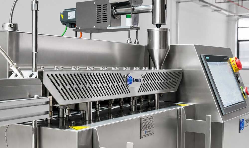
Engineering plastics are compounded in a Twin Screw Extruder by feeding resin with fillers, fibers, pigments, flame retardants, lubricants, or additives, then using controlled heat, shear, mixing, venting, pressure, cooling, and pelletizing to produce stable functional compounds.
Engineering plastics compounding means modifying a base resin to improve its mechanical, thermal, electrical, wear, flame-retardant, dimensional, or processing performance.
The base resin may be PA, PC, PBT, PET, PPS, POM, PEEK, TPU, high-temperature nylon, or another functional polymer. The formula may include glass fiber, carbon fiber, mineral filler, impact modifier, flame retardant, color masterbatch, lubricant, stabilizer, compatibilizer, conductive additive, or processing aid.
The purpose is not only to melt plastic. The purpose is to build a material system that can meet a specific application requirement. For example, an automotive part may need high stiffness and heat resistance. An electrical part may need flame retardancy and insulation. A high-wear component may need better friction and wear resistance.
A twin screw extruder is widely used for this work because it can combine feeding, melting, mixing, devolatilization, pressure building, and pelletizing into one continuous process.
Internal link: Twin Screw Extruder
A twin screw extruder is used because engineering plastics usually need more than simple melting. They need controlled dispersion, staged feeding, high torque, accurate temperature control, vacuum venting, and stable residence time.
Engineering plastics often have one or more processing challenges:
High melt viscosity
High processing temperature
Abrasive fillers or fibers
Heat-sensitive additives
Moisture or volatile release
Strict pellet quality requirements
Tight color and dispersion standards
High mechanical performance targets
Wear and corrosion risk inside the barrel
A single screw extruder can melt and shape prepared material, but it has limited ability to mix complex formulas. A twin screw extruder can use modular screw elements, side feeding, degassing sections, and controlled shear to match different engineering plastic systems.
The practical value of twin screw compounding is process balance. The resin must be melted enough for additive wetting, but not over-sheared. Fibers must be distributed, but not broken too much. Volatiles must be removed, but the vent section must not flood. Output must increase, but torque and temperature must stay inside a safe range.
The basic process flow starts with raw material preparation and ends with cooled, cut, and inspected pellets.
A typical engineering plastics compounding line follows this sequence:
| Process Stage | Main Purpose |
|---|---|
| Material drying | Removes moisture before feeding |
| Main feeding | Feeds base resin and selected additives |
| Melting or softening | Creates a processable polymer melt |
| Filler or fiber side feeding | Adds glass fiber, carbon fiber, mineral filler, or sensitive additives |
| Mixing and dispersion | Distributes additives and builds compound uniformity |
| Vacuum venting | Removes moisture, air, low-molecular volatiles, or odor |
| Pressure building | Stabilizes melt flow before the die |
| Strand or die discharge | Sends melt to cooling and pelletizing |
| Cooling | Solidifies strands or pellets |
| Pelletizing | Cuts material into pellets |
| Inspection and sorting | Detects gels, black specks, color deviation, and size defects |
The exact flow depends on the formula. A glass fiber reinforced PA compound may need side feeding after the polymer is melted. A flame-retardant PC/ABS compound may need careful additive feeding and temperature control. A PEEK compound may need ultra-high temperature control, high torque, and strong devolatilization.
Material preparation begins before the material enters the extruder. Moisture, particle size, bulk density, feeding stability, and additive form can strongly affect output and product quality.
Many engineering plastics are moisture-sensitive. If moisture is not controlled, the melt may show bubbles, voids, strand breakage, molecular weight loss, silver streaks, odor, or reduced mechanical properties. Drying conditions should be set according to resin type and supplier data.
The feeding system should also match the material form. Pellets, powders, regrind, flakes, chopped glass fiber, carbon fiber, flame retardants, and mineral fillers all behave differently in the hopper. Poor flowability can cause bridging, feeding pulses, segregation, and unstable screw filling.
A useful production habit is to record moisture, drying time, feeder trend, and material batch before judging the extruder. Many output or torque problems begin with the material, not the screw.
The twin screw extruder melts engineering plastics through a combination of barrel heating, mechanical shear, screw filling, residence time, and material friction.
Barrel heaters provide the basic temperature profile. Screw rotation moves material forward and creates shear energy. As the resin softens, it begins to wet fillers, pigments, flame retardants, or reinforcement materials. The process must create enough melt quality for mixing without overheating the polymer.
For high-temperature engineering plastics, the melting section must be strong and stable. PEEK is a typical example. Its processing melt range is high, and the compounding system needs high temperature control, high shear-mixing capacity, corrosion-resistant and wear-resistant screw and barrel materials, strong exhaust, and a high-torque drive system.
Internal link: Special Engineering Plastics - PEEK
Fillers and fibers are usually added through a side feeder after the resin has partly or fully melted. This is especially important for lightweight, bulky, abrasive, or breakage-sensitive materials.
If all materials are added through the main feed throat, several problems may appear:
Poor feeding stability
Powder bridging
High friction in the early barrel zones
Glass fiber breakage
Carbon fiber damage
Weak filler wetting
High torque
Poor dispersion
Dust leakage near the feed section
Side feeding allows the polymer melt to receive fillers or fibers at a better process point. The resin can wet the reinforcement more effectively, while the screw can distribute it without exposing it to unnecessary full-length shear.
For glass fiber or carbon fiber compounds, the key is not maximum shear. The key is controlled distribution. Fibers must be spread through the melt, but excessive shear can reduce fiber length and weaken the final material performance.
Screw configuration decides how the compound is conveyed, melted, mixed, vented, compressed, and discharged.
A modular twin screw extruder can use different screw elements for different process tasks. Conveying elements move material forward. Kneading elements add shear and dispersion. Mixing elements improve distribution. Reverse or restriction elements can increase filling and pressure, but they also raise torque and heat. Venting sections create space for moisture and volatile removal.
For engineering plastics, the screw design should be matched to the formula goal:
| Formula Need | Screw Design Focus |
|---|---|
| Glass fiber reinforcement | Controlled side feeding and limited fiber breakage |
| Carbon fiber compound | Gentle distribution and stable feeding |
| Mineral-filled compound | Strong wetting, high torque capacity, wear control |
| Flame-retardant compound | Good dispersion with limited thermal degradation |
| Color compound | Pigment dispersion and color consistency |
| High-temperature PEEK compound | High-temperature stability, high torque, strong devolatilization |
| Heat-sensitive blend | Lower shear, shorter residence time, better cooling |
| Conductive compound | Uniform network distribution without over-shearing |
LEMIX twin screw extruders use modular screw and barrel systems. Screw material and screw combination can be customized according to materials and formulas, while barrel openings can be designed for feeding, degassing, and venting.
Temperature should be controlled by both barrel setpoints and real process response. The setpoint is only the starting point. Actual material temperature also depends on screw speed, feed rate, shear, filler loading, viscosity, cooling capacity, and residence time.
Engineering plastics often need a narrow balance. If the temperature is too low, the resin may not melt or wet additives well. Torque and pressure may rise. If the temperature is too high, the material may degrade, discolor, release odor, lose mechanical performance, or create black specks.
High-temperature materials such as PEEK need precise heating and cooling. Heat-sensitive additives and flame-retardant systems may need a milder profile. Filled compounds may need stronger cooling because filler friction can raise material temperature.
LEMIX twin screw extruders include barrel heating and cooling systems, pressure and temperature sensors, and HMI control. The high cooling capacity design helps create a wider process window for demanding materials.
Torque shows the mechanical load created by the material inside the extruder. Engineering plastics often create high torque because they may have high viscosity, high filler loading, or strong reinforcement content.
High torque can mean the process is heavily loaded. It may come from low melt temperature, high feed rate, high filler content, insufficient melting, die restriction, screw wear, barrel wear, or overly aggressive screw elements. Low torque can mean the barrel is underfilled, the material is too hot, or the screw is not providing enough mixing work.
Torque should be monitored with feed rate, screw speed, melt pressure, and product quality. A stable torque trend usually means the material feed, melting, and discharge are repeatable. A moving torque trend often reveals a problem before pellet defects become obvious.
LEMIX twin screw extruders use high-power drive solutions and high-torque shaft designs to support high-load materials and stable operation.
Vacuum venting removes moisture, air, low-molecular substances, residual volatiles, and odor from the melt. This is important for many engineering plastics because trapped gas can reduce mechanical performance and create visible defects.
Weak venting may cause:
Bubbles
Internal voids
Strand breakage
Poor pellet appearance
Lower mechanical strength
Odor
Die instability
Surface defects
Pressure fluctuation
The venting section must be designed correctly. If the screw is too full near the vent, material can flood the vent port. If the melt is not fully formed before venting, devolatilization may be weak. If vacuum is unstable, defects may appear intermittently.
The same principle is critical in pharmaceutical hot melt extrusion. LEMIX pharmaceutical extrusion systems use a dedicated large-pitch vacuum section and multistage high-vacuum system to remove moisture, residual solvents, and low-molecular impurities. This shows the same process logic: stable quality depends on controlled feeding, melting, venting, and residence time.
Internal link: Pharmaceutical Extrusion
PEEK compounding is more demanding because of its high processing temperature, high melt viscosity, and strict performance requirements.
PEEK may be reinforced or modified to improve wear resistance, impact performance, corrosion resistance, friction behavior, or high-temperature performance. Its compounding process needs accurate high-temperature control, high-torque drive capacity, strong shear and dispersion, suitable screw metallurgy, side feeding for fibers, and effective devolatilization.
For PEEK compounds, several details matter:
The barrel and die must tolerate high processing temperature.
Screw and barrel materials must resist high-temperature wear and corrosion.
Glass fiber or carbon fiber should be side-fed to reduce breakage.
The screw should distribute fibers without excessive shear.
Vacuum venting should remove moisture and low-molecular volatiles.
Torque reserve is needed to prevent overload shutdown.
Pellet quality must be checked carefully because defects can represent high material loss.
A practical process view is that PEEK compounding should be treated as a high-value, high-risk process. Temperature, torque, residence time, screw wear, and cleaning quality must all be controlled together.
Downstream pelletizing affects the final usability of engineering plastic compounds. Even if the melt is well compounded, poor cooling or cutting can create pellet defects.
Common downstream problems include:
| Downstream Issue | Possible Defect |
|---|---|
| Uneven strand cooling | Deformed pellets or sticking |
| Poor cutter condition | Long tails, fines, irregular size |
| Unstable die flow | Different strand thickness |
| Water carryover | Surface moisture or handling problems |
| Strand breakage | Output interruption and waste |
| Wrong pelletizer speed | Oversize or undersize pellets |
| Poor conveying after cutting | Dust, fines, or pellet damage |
For high-value engineering plastics, pellet quality should not be checked only by occasional sampling. Real-time inspection can help identify defects that appear between manual checks.
LEMIX in-Line Plastic Pellet Inspection supports continuous pellet inspection and sorting. It can help detect defects such as burnt material, gels, size and cutting problems, cross contamination, yellowing, and color deviation.
Internal link: in-Line Plastic Pellet Inspection
Engineering plastic defects often come from feeding, moisture, poor melting, weak dispersion, degradation, venting failure, wear, cleaning issues, or downstream instability.
| Defect | Common Cause | First Check |
|---|---|---|
| Bubbles | Moisture, weak vacuum, poor drying | Dryer, moisture level, vent section |
| Black specks | Degradation, residue, dead zones | Screw cleaning, temperature, residence time |
| Poor dispersion | Weak screw design or low mixing energy | Screw configuration, torque, melt quality |
| Fiber breakage | Excessive shear or wrong feed point | Side feeder position, screw elements |
| Color streaks | Poor pigment dispersion or contamination | Feeding, screw cleaning, mixing section |
| Pellet size variation | Cutting or pressure instability | Die, strand cooling, pelletizer |
| Low mechanical strength | Poor wetting, fiber damage, moisture | Mixing quality, fiber length, drying |
| High torque | High viscosity, overfeeding, low temperature | Feed rate, temperature, pressure |
| Output fluctuation | Feeding pulses, wear, die restriction | Feeder trend, barrel wear, screen |
| Yellowing | Overheating or long residence time | Temperature profile, screw speed, dead zones |
The fastest troubleshooting method is to compare defect timing with process trends. If defects appear after a new material batch, check material and moisture first. If defects appear after long running time, check cooling, residue, die buildup, or wear. If defects appear after output increase, check torque, venting, pressure, and downstream cutting.
Wear is a major issue in engineering plastics compounding because many formulas contain abrasive fillers or fibers. Glass fiber, carbon fiber, mineral fillers, flame retardants, and high-hardness additives can wear screw elements, barrels, and die parts.
Wear changes screw-to-barrel clearance. As clearance increases, conveying efficiency, pressure stability, and mixing performance can decline. The same screw speed may no longer produce the same output. The line may show torque drift, pressure fluctuation, poor dispersion, or more product variation.
Wear should be checked when the same formula and same settings no longer give the same result. It should also be checked in high-filler and high-temperature production, where wear can develop faster.
Internal link: Barrel Wear Measurement Device PROMAC-S
Cleaning matters because engineering plastics can leave high-temperature residue, pigments, fillers, degraded polymer, carbonized particles, and deposits on screws, die plates, breaker plates, nozzles, shafts, and mandrels.
Poor cleaning can cause cross contamination, black specks, color drift, gels, pressure instability, and long changeover time. For high-cost engineering plastics, a small amount of residue can create expensive waste in the next run.
Traditional flame burning or aggressive manual cleaning may damage precision screw surfaces. A non-destructive cleaning method is safer for long-term screw life.
LEMIX PRO-COOL Screw Cleaning Machine is designed for non-destructive high-pressure water cleaning of screws and extrusion components. It helps remove polymer residue and contaminants without flame burning, manual brushing, toxic smoke, or surface damage.
Internal link: PRO-COOL Screw Cleaning Machine
A lab trial should be used to confirm the processing window before scaling to production. This is especially useful for expensive engineering plastics, high-filler formulas, new flame-retardant systems, new color systems, or fiber-reinforced compounds.
A useful lab trial should test:
Drying condition
Feeding stability
Melting window
Screw configuration
Filler or fiber feeding point
Screw speed and feed rate balance
Torque response
Vacuum venting effect
Strand quality
Pellet appearance
Color and dispersion
Mechanical test direction
Residence time sensitivity
Cleaning difficulty
LEMIX Lab Type Twin Screw Extruder can support R&D, formulation trials, small-batch testing, and scale-up study. Trial data should be recorded in a way that can guide pilot and production settings.
Internal link: Lab Type Twin Screw Extruder
Good process records help reduce repeated troubleshooting. Engineering plastics often fail because a small upstream change is missed.
Useful records include:
Resin type and batch
Moisture level and drying condition
Additive type and dosage
Filler or fiber loading
Fiber length and feeding method
Screw configuration
Barrel temperature profile
Actual material temperature if available
Screw speed
Feed rate
Torque trend
Melt pressure trend
Vacuum level
Die temperature
Cooling condition
Pelletizer speed
Pellet defect type
Cleaning history
Screw and barrel wear condition
A strong process record should show relationships, not isolated values. The most useful field record often answers three questions: what changed first, what changed next, and what defect appeared last.
LEMIX supports engineering plastics compounding through twin screw extrusion equipment, lab machines, particle inspection, maintenance devices, and Spare Parts.
| Process Need | LEMIX Product Support |
|---|---|
| High-torque compounding | Twin Screw Extruder |
| Formula trial and scale-up | Lab Type Twin Screw Extruder |
| PEEK and high-temperature processing | Twin Screw Extruder with suitable screw, barrel, heating, and cooling design |
| Pellet quality control | in-Line Plastic Pellet Inspection |
| Screw and barrel wear control | PROMAC-S Barrel Wear Measurement Device |
| Screw and component cleaning | PRO-COOL Screw Cleaning Machine |
| Cooling stability | PRO-CLEAN Water Cooling Channel Cleaning Machine |
| Long-term maintenance | Screw elements, barrels, shafts, gearboxes |